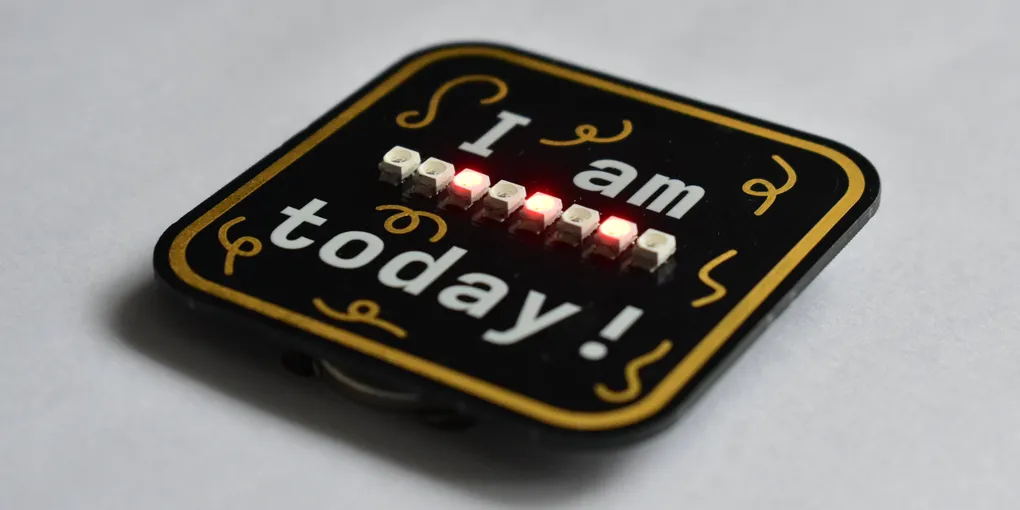
How I made the Binary Birthday Badge
This project began with a stupid idea. What if there were a birthday badge that used lights to show your age? What if it used binary?
Circuit design
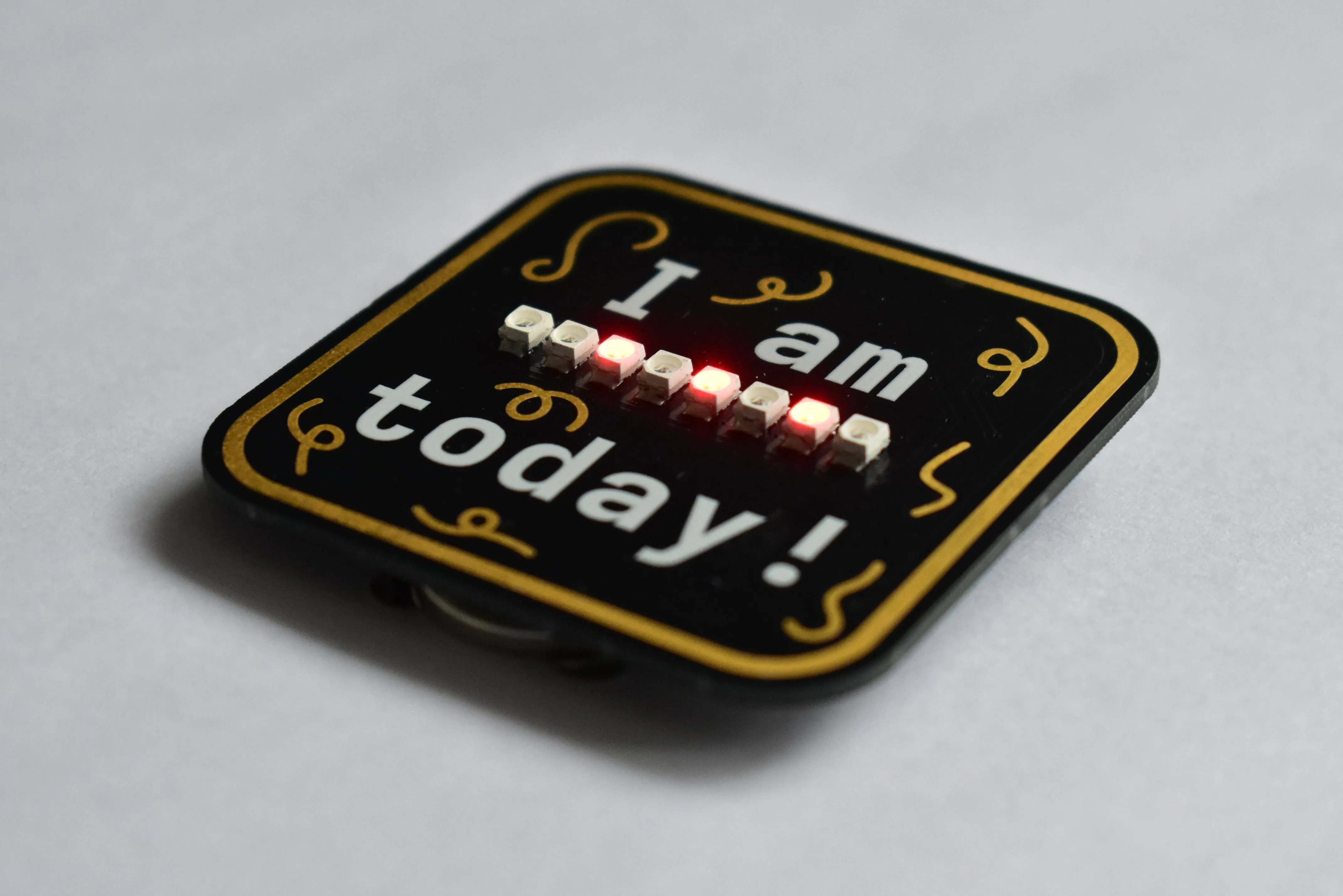
I decided to use 8 LEDs to display the age. While 7 would’ve been enough to display any age up to 127, I decided to go with 8, as that would be 8 bits, a byte, and this also future-proofs it, in case anyone turns 255 years old.
For the brains of this project, I chose the Attiny85 microcontroller due to its small size, low power and low cost. The problem with this, is that it only has 6 I/O ports, of which I only want to use 5, and I needed to control 8 LEDs and be able to detect the state of at least 2 buttons.
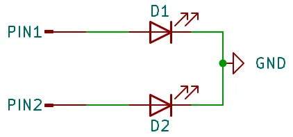
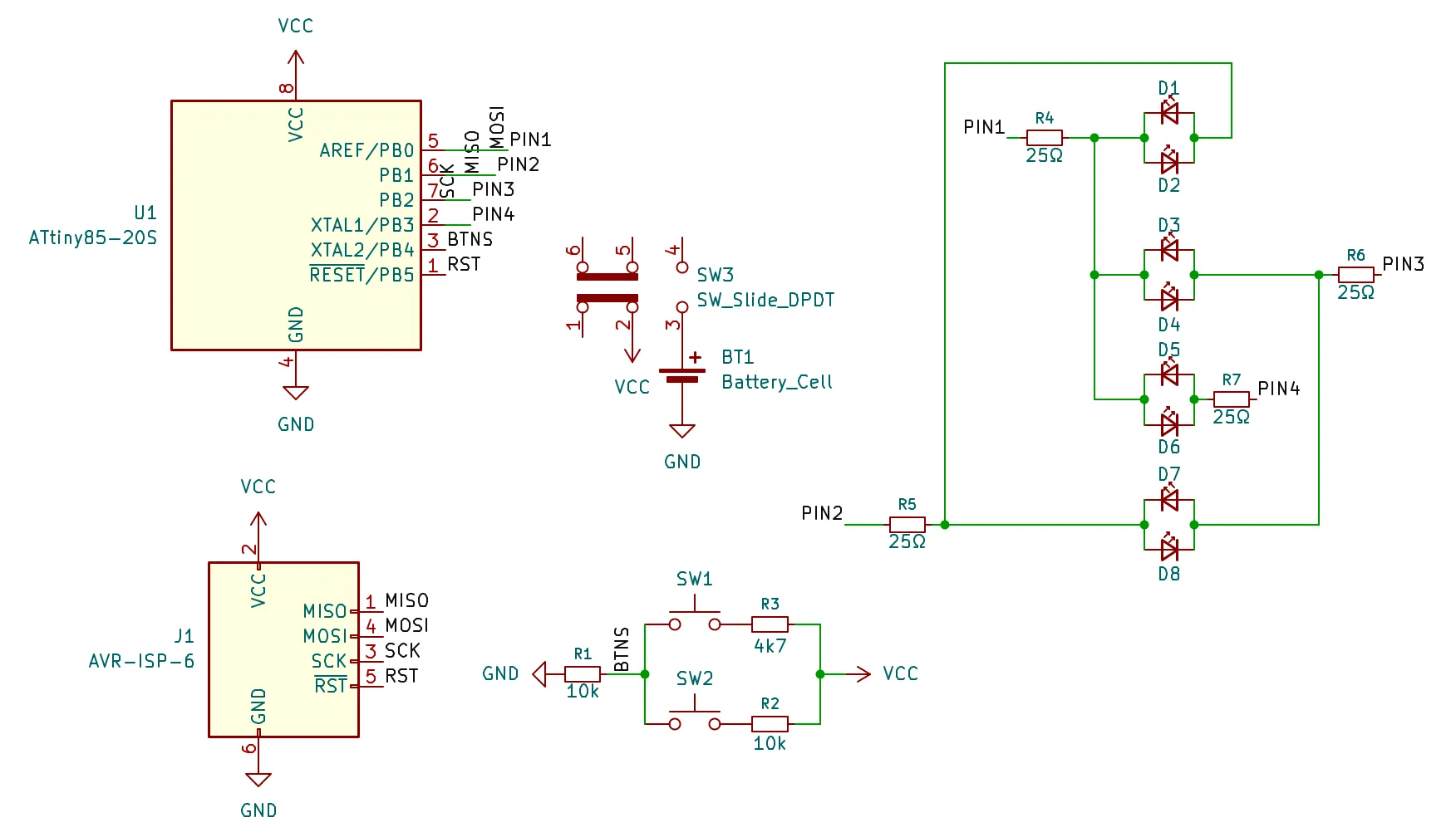
Firstly, to fix the issue with the LEDs, I used a technique called “charlieplexing”. To explain this, first think about a situation where you have 2 LEDs and 2 I/O ports. The most obvious, and sensible in this basic example, way to control the LEDs is to connect cathode of each LED to ground, and the anodes to separate I/O pins which you can set high to turn the LED on.
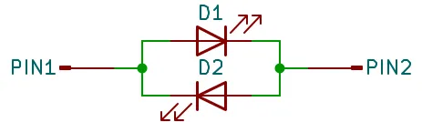
However, another way you could do it is to connect the anode and cathode of an LED to the 2 I/O ports. Then, for the next LED, you can connect it to the same ports, but with the reverse polarity. That way, to turn on 1 LED, you would set the first output high, and the other low, and for the other, you’d set the first output low and the other high. Each LED can be controlled by setting the pin connected to its anode high and the pin connected to its cathode low. This is the basis behind charlieplexing.
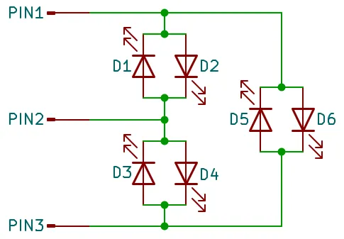
With 3 or more pins, you do something similar, but you can have up to one LED per anode-cathode pin pair. This means that with N pins, for each of N anode pins, there are (N-1) possible cathode pins, meaning you can control N(N-1) LEDs.
This means that with 3 pins you can control 3×2 = 6 LEDs, and with 4 you can control 4×3=12 pins and for my 8 LEDs, I will actually only need 4 pins.
One slight issue with the way that charlieplexing works, is that you can essentially only turn 1 LED on at a time. The pins not being used are set to a floating state, to ensure only the correct LED is switched on.
While this sounds like a huge issue, as I need to be able to have up to 8 LEDs on at once, there is a solution. By rapidly switching which LED is on, the human eye views the LEDs as all being on all the time. This is called persistence of vision. It does make the LEDs dimmer, but that shouldn’t be an issue if the LEDs are bright enough to begin with.
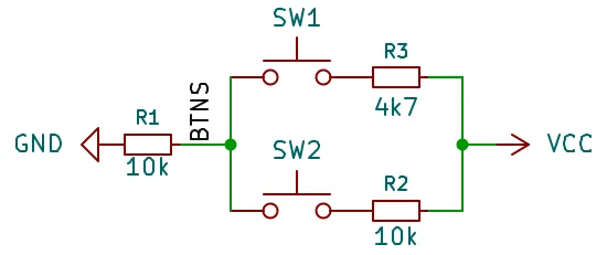
With four pins used for the LEDs, there is one pin left for the 2 buttons. Luckily, there is still a way I can do this. Four of the pins on the attiny are analogue inputs. This means that they can detect different voltages, not just a high or low voltage.
You can use this by creating a voltage divider, like in the diagram below, which applies a different voltage to the input for different combinations of buttons, meaning I only need one input pin.
To power the board, I went with a CR2032 battery due to its small size, and, as its 3V, I don’t need any circuitry to change the voltage.
Once I had all this, I designed the schematic in KiCad.
PCB Design
The aesthetics of this are almost as important as the electronics, as noone would wear a badge if it looks horrible.
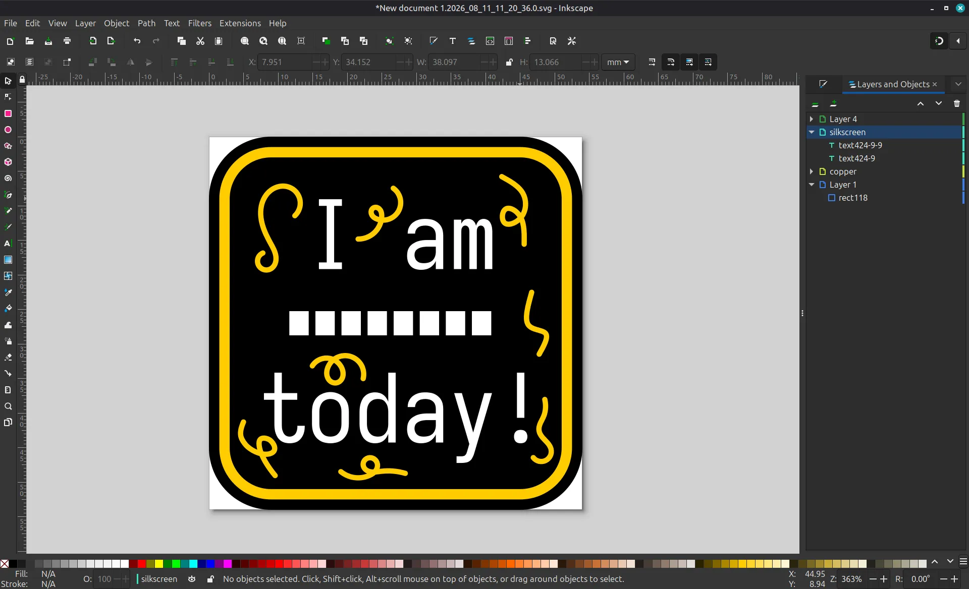
I started the design in Inkscape, with a separate layer for the board, silkscreen and copper. I then exported each layer as an svg and imported them into KiCad using the Import Graphics tool in the PCB editor. I did have some trouble importing the text, so I just used the text feature in the KiCad, rather than the text from the design.
The PCB design is quite simple. It is a 2 layer pcb, with a ground plane on both layers. All of the components apart from the LEDs are placed on the back of the board to keep them hidden.
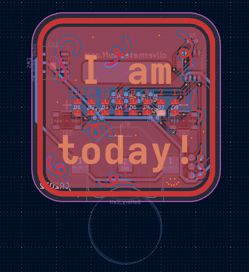
Above each LED, I added the number that it represents on the copper layer, but didn’t remove the solder mask there, so that it is not very obvious, but can be read if necessary.
Programming
I ordered the boards and soldered the components to them.
When designing the board, I added AVR header pins as contacts, which I could use to program the Attiny85. I had an ISP programmer and I used some protoboard and pogo pins to create a jig for programming, which meant I didn’t have to solder a physical connector to it.
The code was written in C, then compiled and uploaded to the board. It starts off with an age of 0, where it plays a chaser-style animation with the LEDs. Then the user can press the plus and minus button to set the age. By holding down on these buttons, the age will start going up or down quicker. While the badge is in age setting mode, the LEDs flash if no buttons are pressed. To lock the age, the user can hold down both buttons, stopping the flashing, and reducing the chance of the age getting accidentally changed. To change the age again, the user just needs to hold down both buttons again.
Conclusion
I’m really happy with the final result. The badge works as intended, and I think it looks pretty cool.
You can buy one now here.