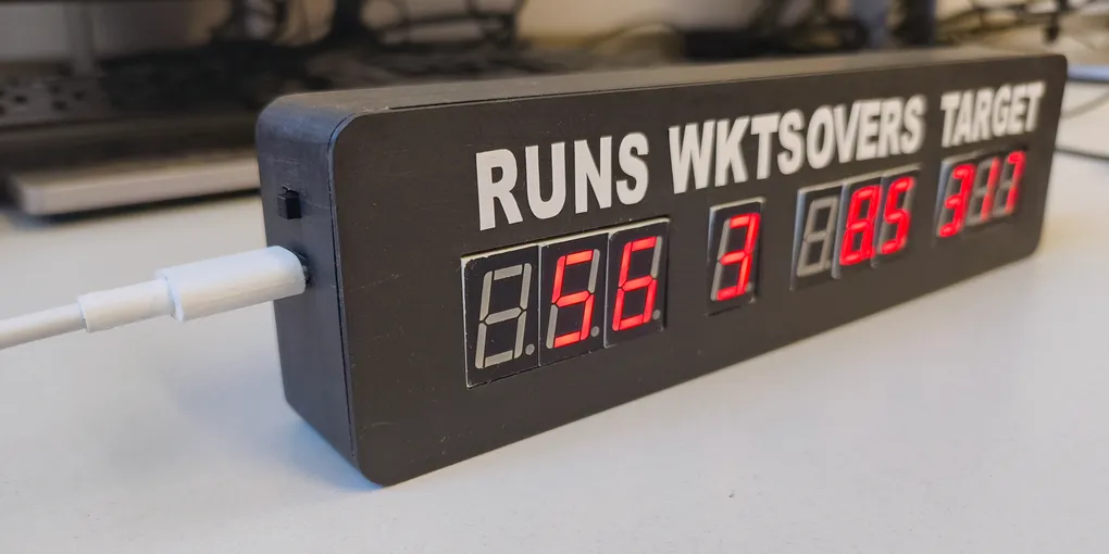
Desktop Cricket Scoreboard
For my GCSE Design and Technology coursework, I had to design and make something sports-related. I wanted to do something electronics based, so I decided to make a desktop cricket scoreboard, for keeping track of ongoing matches.
It started with drawings, which at the time of writing I could not find, to decide what I wanted it to look like. I decided to go for a classic cricket scoreboard look, with a black body, white text and with 7-segment LED displays to display the score.
I selected the ESP32-C3 as the main microcontroller for this project due to its built-in WiFi capabilities. To control the displays, I used 2 MAX7219 drivers, which can control up to eight digits each. I used the first one for the first eight digits, and the second one for the last two. The ESP32-C3 uses 3.3V outputs, but the MAX7219 uses 5V input signals, so I added a logic level converter in between them, increasing the voltage of the signals, allowing them to function together.
The way the MAX7219s work is with multiplexing. The 7-segment displays are common-cathode, so each segment in a display has the same negative pin (cathode), but a different positive pin (anode).
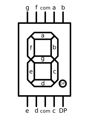
So, for example, to display the number 1, the common cathode, com, must be connected to ground, and pins b and c must be connected to a positive voltage.
Each MAX7219 has eight digit outputs and eight segment outputs, one for each digit and segment. The digit outputs are connected to the common cathode of the corresponding 7-segment display, and the segment outputs are connected to the anode corresponding to that segment on each display.
To control a single digit, the MAX7219 pulls the cathode to ground for that digit, and gives the anode for each segment that should be lit a positive voltage. It does this for each digit in turn, and when it switches between digits quickly, the human eye sees all the digits at once, due to persistence of vision.
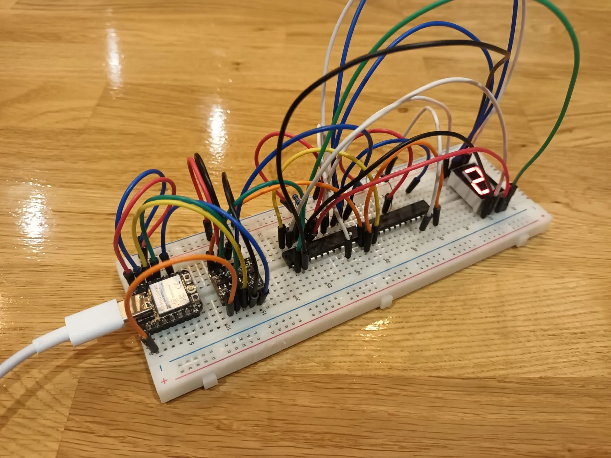
While the Seeed Studio XIAO ESP32-C3 board that I was using had a USB-C port, I wanted more control over where it was placed, so I added an extra USB-C breakout connector for powering the display, as well as a switch to turn it on and off.
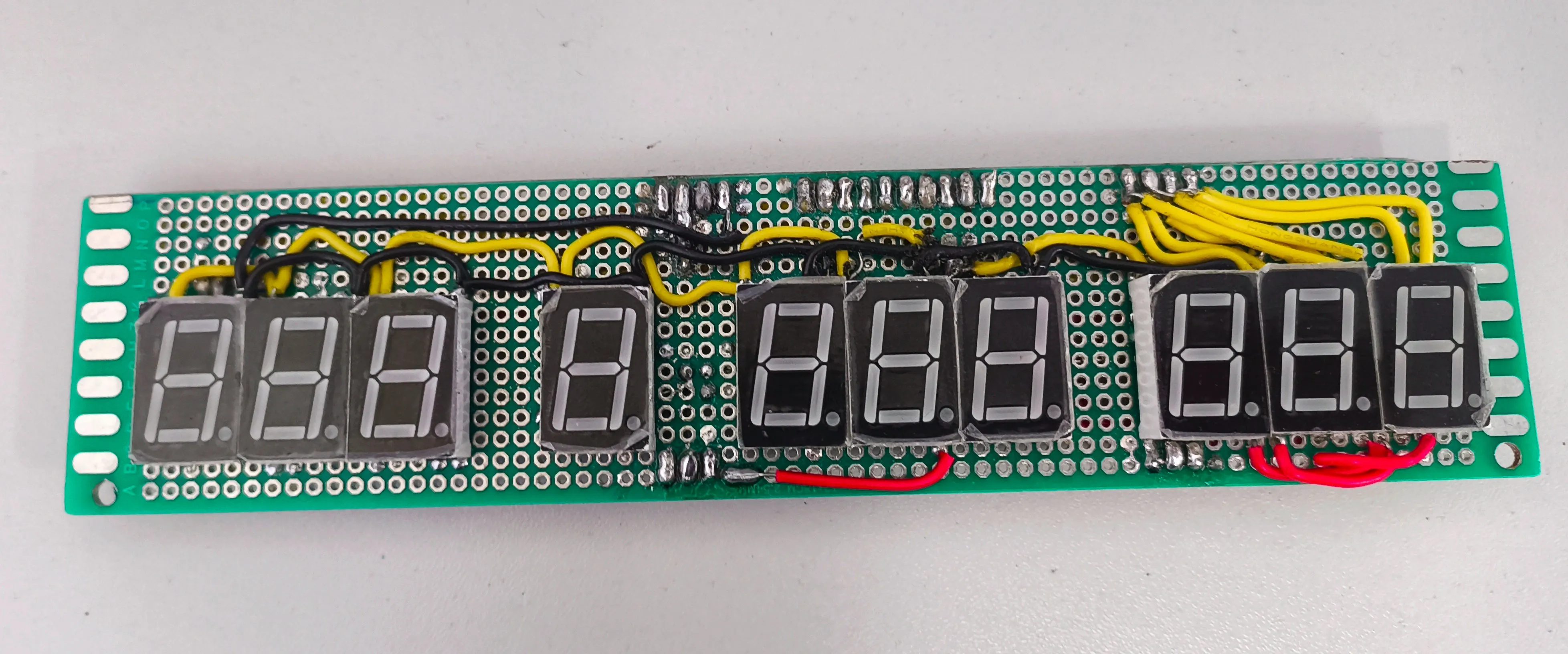
Once I had the basic circuit design done, I had to work out how to actually make it. While I considered designing a PCB (Printed Circuit Board) for this project, I eventually settled on making the circuit on two pieces of protoboard and attaching them with header pins. The front board would have the displays, and the back piece would have the ESP32, the MAX7219s and all the other pieces. This meant that I just needed headers to connect the MAX7219s’ outputs to the displays.
Deciding to hand solder everything was a decision I regret. It took weeks of work. As you can see in the images below, the wiring is very complicated. This also led to the biggest issue with this project. There was a short somewhere in that mess of wiring. Despite hours spent trying to find it, I did not succeed. This meant that I could not individually control each segment, making the display useless.
In the end, for my coursework, I took photos with the numbers that the display could show, modelling what it would look like if it were working.
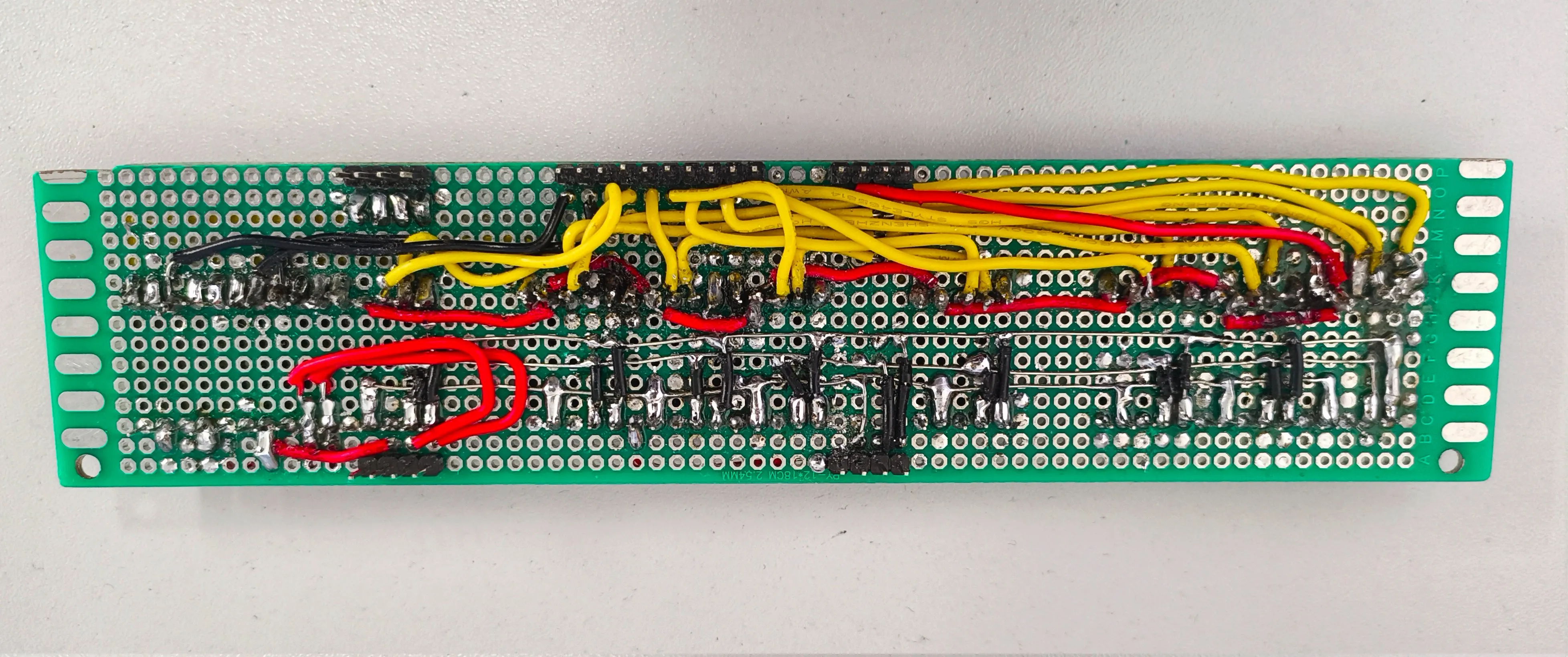
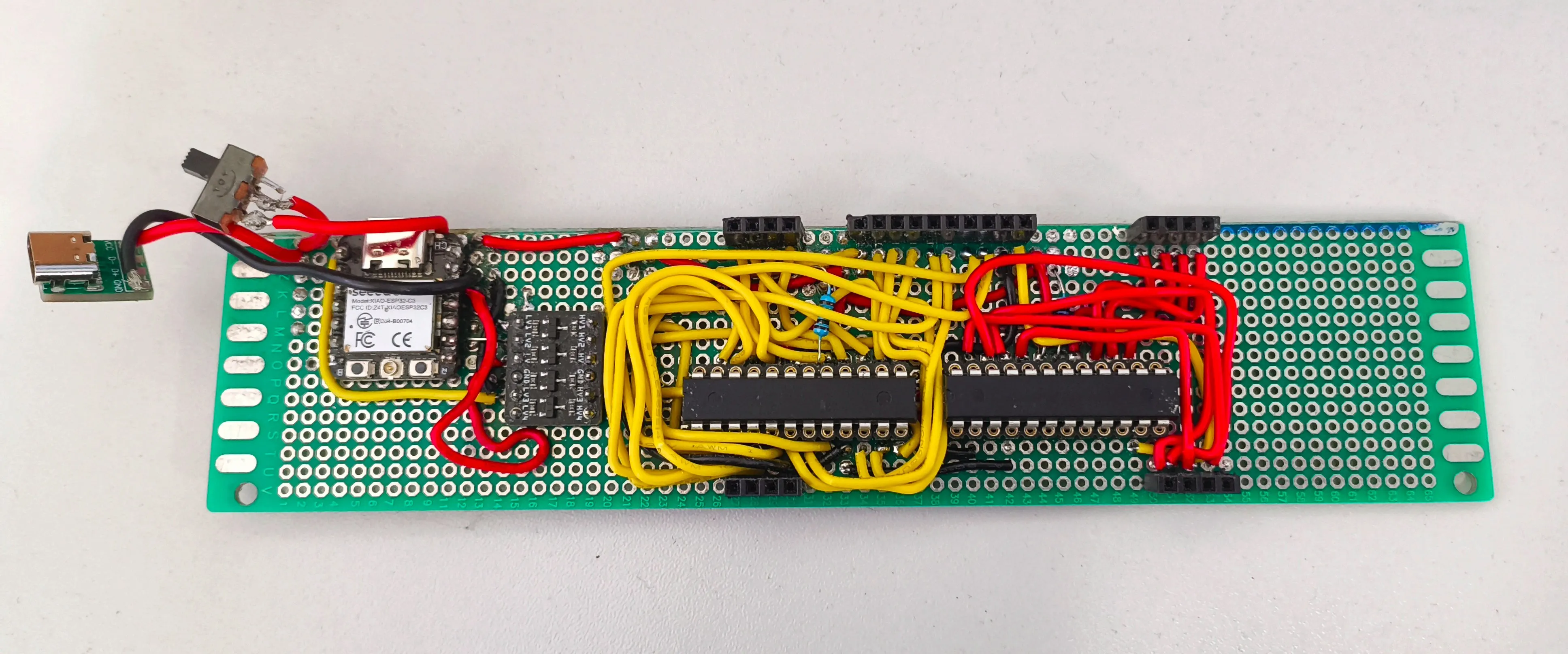
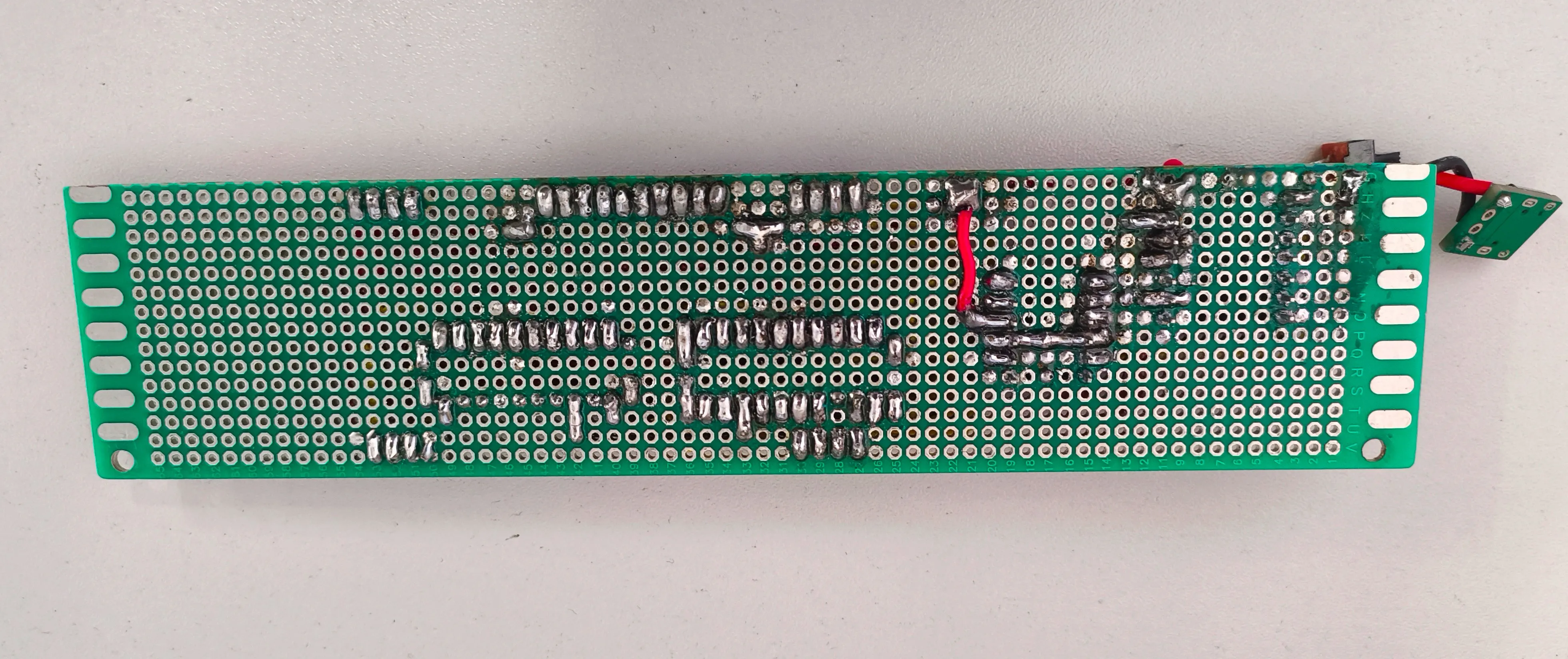
Once I had done that, I had to work on the case. I designed the case in Autodesk Fusion then 3D-printed it. It has two parts and uses screws to stay together and align the circuit boards, while still allowing disassembly if necessary. Finally, I sanded it and applied some custom-cut vinyl labels to show which part of the score each number represents.
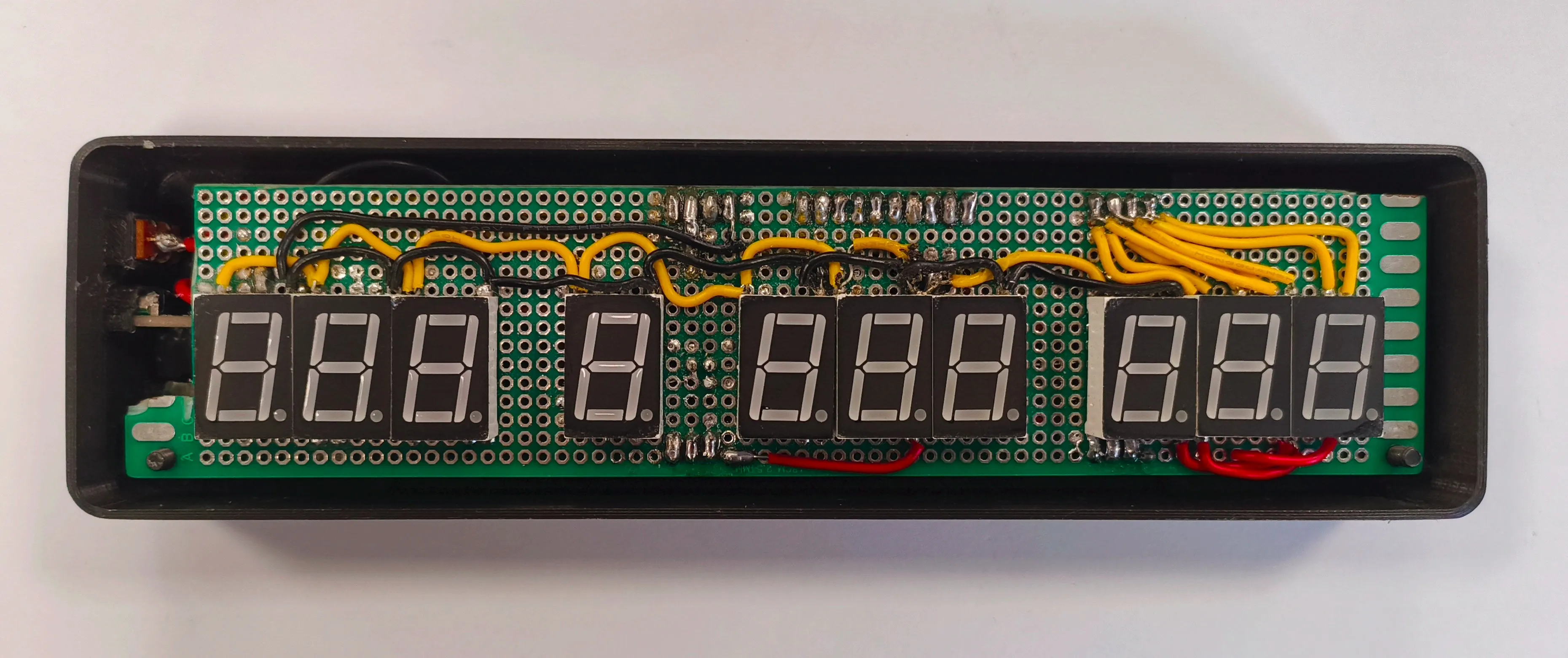
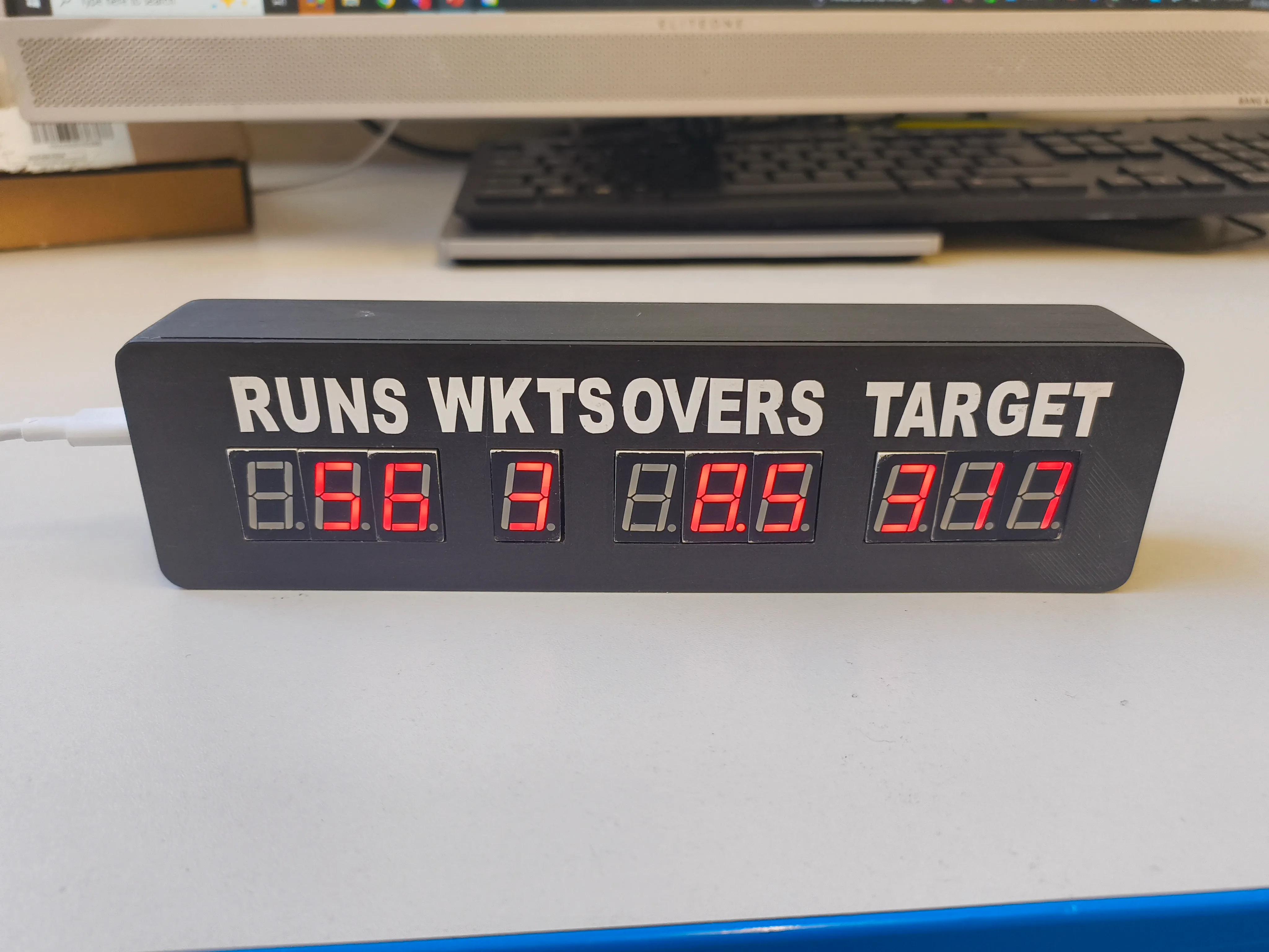

There are a few things that I would change if I made this again. The most important being, designing a PCB to make assembly much quicker and less error-prone. I also considered adding a battery during design, but decided against it due to concerns about space and complexity, as I had a limited amount of time. If I designed a PCB, this would be slimmer than the current two-protoboard solution, allowing more room for a battery. Another thing I would add is an adjustable stand, allowing the user to better position the display, making it more ergonomic to read.
Overall, I am happy with the project and I did end up getting a good grade for it. It allowed me to learn more about electronic design and 3D printing, while also teaching me to consider manufacturing processes during the design process, to ensure that the product is easy to make.